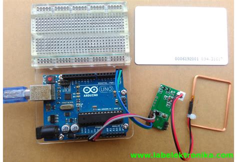
125khz rfid reader circuit diagram The DV103001 developer’s kit includes Contactless Programmer, ASK, FSK, PSK reference . Method 2: Looking for signs on the card: Some cards may have visible indications indicating the presence of RFID or NFC technology. Look for any logos or symbols on the card that suggest contactless communication. .
0 · usb rfid reader 125khz software
1 · rfid reader 125khz arduino
2 · handheld 125khz rfid reader writer
3 · grove 125khz rfid datasheet
4 · 125khz rfid reader writer
5 · 125khz rfid reader module
6 · 125khz rfid reader long range
7 · 125khz rfid reader keyboard
$7.95
The DV103001 developer’s kit includes Contactless Programmer, ASK, FSK, PSK reference .
microID™ 125 kHz RFID System Design Guide INCLUDES: • Passive RFID Basics Application .READER, INTERROGATOR RFID reader is used to activate passive tag with RF energy and to extract information from the tag. For this function, the reader includes RF transmission, receiving and data decoding sections. In addition, the reader includes a serial communication (RS-232) capa-bility to communicate with the host computer. Depend-
The DV103001 developer’s kit includes Contactless Programmer, ASK, FSK, PSK reference readers, and reference design guide. The reference design guide includes schematics for readers and contactless programmer as well as in-depth document for antenna circuit designs.microID™ 125 kHz RFID System Design Guide INCLUDES: • Passive RFID Basics Application Note • MCRF200 Data Sheet • MCRF250 Data Sheet • Contact Programming Support • RFID Coil Design • FSK Reader Reference Design • PSK Reader Reference Design • ASK Reader Reference Design • FSK Anti-Collision Reader Reference Design
A typical 125KHz RFID reader circuit diagram generally consists of an antenna, a power supply, a microcontroller, and an interface board. Each of these individual components plays a key role in the successful implementation of an RFID reader. In this tutorial, we are going to interface RDM6300 RFID Reader Module with Arduino Nano. The RDM6300 RFID Reader is one type of RFID module with a 125 kHz frequency. This RFID module can read data from 125 kHz compatible read .RFID Circuit & PCB Design Notes. It’s usually very important that the voltage supply to an RFID reader is protected from ripple and interference. Where you have noisy electronics in the proximity: A simple RC filter of 10R and 1000uF will go a long way to preventing interference.Follow these steps to build your 125kHz RFID reader circuit: Connect the MFRC522 RFID module to the Arduino Uno board using jumper wires. Set up the circuit on the breadboard, ensuring proper connections. Add LEDs and resistors to indicate the status of the RFID reader. Upload the necessary code to the Arduino board. Test the circuit by placing .
Learn How to interface a RDM6300 125KHz RFID Reader Module with Arduino. using RDM6300 RFID Module example code, circuit, pinout, library.
In this article, we will delve into the fascinating world of RFID readers and explore their circuit diagram. At its core, an RFID reader circuit consists of three essential components: an antenna, a transceiver, and a decoder.arduino-rfid-RDM6300 Code, wiring diagrams, and documentation describing how to interface an Arduino with RDM6300 module to read 125kHz EM4100 tags. When a card with the correct tag ID is read, as defined in the code, a relay is activated which can, for example, unlock a maglock.READER, INTERROGATOR RFID reader is used to activate passive tag with RF energy and to extract information from the tag. For this function, the reader includes RF transmission, receiving and data decoding sections. In addition, the reader includes a serial communication (RS-232) capa-bility to communicate with the host computer. Depend-
The DV103001 developer’s kit includes Contactless Programmer, ASK, FSK, PSK reference readers, and reference design guide. The reference design guide includes schematics for readers and contactless programmer as well as in-depth document for antenna circuit designs.
microID™ 125 kHz RFID System Design Guide INCLUDES: • Passive RFID Basics Application Note • MCRF200 Data Sheet • MCRF250 Data Sheet • Contact Programming Support • RFID Coil Design • FSK Reader Reference Design • PSK Reader Reference Design • ASK Reader Reference Design • FSK Anti-Collision Reader Reference Design A typical 125KHz RFID reader circuit diagram generally consists of an antenna, a power supply, a microcontroller, and an interface board. Each of these individual components plays a key role in the successful implementation of an RFID reader. In this tutorial, we are going to interface RDM6300 RFID Reader Module with Arduino Nano. The RDM6300 RFID Reader is one type of RFID module with a 125 kHz frequency. This RFID module can read data from 125 kHz compatible read .RFID Circuit & PCB Design Notes. It’s usually very important that the voltage supply to an RFID reader is protected from ripple and interference. Where you have noisy electronics in the proximity: A simple RC filter of 10R and 1000uF will go a long way to preventing interference.
Follow these steps to build your 125kHz RFID reader circuit: Connect the MFRC522 RFID module to the Arduino Uno board using jumper wires. Set up the circuit on the breadboard, ensuring proper connections. Add LEDs and resistors to indicate the status of the RFID reader. Upload the necessary code to the Arduino board. Test the circuit by placing .Learn How to interface a RDM6300 125KHz RFID Reader Module with Arduino. using RDM6300 RFID Module example code, circuit, pinout, library. In this article, we will delve into the fascinating world of RFID readers and explore their circuit diagram. At its core, an RFID reader circuit consists of three essential components: an antenna, a transceiver, and a decoder.
securing rfid tags

usb rfid reader 125khz software

Nfc-frog. Kick-ass contactless credit card reader. With nfc-frog you can extract .
125khz rfid reader circuit diagram|usb rfid reader 125khz software