light rfid chip circuit RFID sensor tags consist of an antenna, a radio frequency integrated circuit chip (RFIC), and at least one sensor. An ideal tag can communicate over a long distance and be seamlessly. NFC Key fobs NFC Gadgets. . The most resistant NFC Tag, for industrial use. .
0 · rfid sensor for led light
1 · rfid light blinking
2 · rfid flashing led light
3 · rfid card arduino
4 · arduino rfid sensor
5 · arduino rfid reader circuit diagram
6 · arduino rfid light
7 · arduino rfid interference
Auburn Sports Network game day coverage begins three hours prior to kickoff. Tiger .

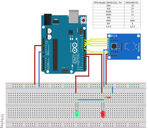
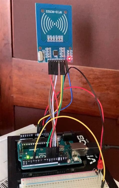
In this tutorial, you will build a device that uses RFID detection to turn on an LED light. This project provides an introduction to using RFID sensors to control responses with an . In this tutorial, you will build a device that uses RFID detection to turn on an LED light. This project provides an introduction to using RFID sensors to control responses with an Arduino. The RC522 RFID module is based on the popular MFRC522 RFID reader chip from NXP. These modules are cheap and available from most online stores. MFRC522 is a highly integrated RFID reader/writer IC for contactless communication at 13.56 MHz. The MFRC522 reader supports ISO/IEC 14443 A/MIFARE and NTAG.
RFID sensor tags consist of an antenna, a radio frequency integrated circuit chip (RFIC), and at least one sensor. An ideal tag can communicate over a long distance and be seamlessly. Yes, they have a tiny chip inside them. The chip is poweed from the coil antenna, the rectifier and a small capacitor are generally implemented on the chip but a bit of extra capacitace can be implemented on in the film to fine tune the resonant frequency of the antenna.In this video, we learn about how RFID works and we see how RFID chips are designed. The main concepts such as backscatter modulation and energy harvesting i.Radio Frequency Identification (RFID) systems use radio frequency to identify, locate and track people, assets, and animals. Passive RFID systems are composed of three components – an interrogator (reader), a passive tag, and a host computer. The tag is composed of an antenna coil and a silicon chip that includes basic modulation circuitry .
Radio Frequency Identification (RFID) systems use radio frequency to identify, locate and track people, assets and animals. Passive RFID systems are composed of three components – a reader (interroga-tor), passive tag and host computer. The tag is composed of an antenna coil and a silicon chip that includes basic modulation circuitry and .
rfid sensor for led light
This paper presents a passive HF-band tag chip supporting ISO/IEC 14443 type A/B protocol with low-cost and low-power consumption. In the Analog Front End, a bridge rectifier with 73.76% power conversion efficiency is presented to accomplish RF-dc conversion. In this article we are going to take a tour on RFID circuit technology. We will be exploring how RFID tags and readers work, how to interface RFID module (RC522) with Arduino and extract some useful information from the RFID tags. RFID chips are integrated circuits inside RFID tags. They are small, highly integrated microchips that contain a logical control unit, memory, and transceiver for decoding, decrypting, and error checking. In this tutorial, you will build a device that uses RFID detection to turn on an LED light. This project provides an introduction to using RFID sensors to control responses with an Arduino.
The RC522 RFID module is based on the popular MFRC522 RFID reader chip from NXP. These modules are cheap and available from most online stores. MFRC522 is a highly integrated RFID reader/writer IC for contactless communication at 13.56 MHz. The MFRC522 reader supports ISO/IEC 14443 A/MIFARE and NTAG.
rfid light blinking
RFID sensor tags consist of an antenna, a radio frequency integrated circuit chip (RFIC), and at least one sensor. An ideal tag can communicate over a long distance and be seamlessly. Yes, they have a tiny chip inside them. The chip is poweed from the coil antenna, the rectifier and a small capacitor are generally implemented on the chip but a bit of extra capacitace can be implemented on in the film to fine tune the resonant frequency of the antenna.
In this video, we learn about how RFID works and we see how RFID chips are designed. The main concepts such as backscatter modulation and energy harvesting i.
Radio Frequency Identification (RFID) systems use radio frequency to identify, locate and track people, assets, and animals. Passive RFID systems are composed of three components – an interrogator (reader), a passive tag, and a host computer. The tag is composed of an antenna coil and a silicon chip that includes basic modulation circuitry .Radio Frequency Identification (RFID) systems use radio frequency to identify, locate and track people, assets and animals. Passive RFID systems are composed of three components – a reader (interroga-tor), passive tag and host computer. The tag is composed of an antenna coil and a silicon chip that includes basic modulation circuitry and .
This paper presents a passive HF-band tag chip supporting ISO/IEC 14443 type A/B protocol with low-cost and low-power consumption. In the Analog Front End, a bridge rectifier with 73.76% power conversion efficiency is presented to accomplish RF-dc conversion. In this article we are going to take a tour on RFID circuit technology. We will be exploring how RFID tags and readers work, how to interface RFID module (RC522) with Arduino and extract some useful information from the RFID tags.
4 types de tags nfc
node red nfc tag

rfid flashing led light
The "hello, world" example that appeared in the first edition of K&R has become the model for an introductory program in most programming textbooks. The program prints "hello, world" . See more
light rfid chip circuit|rfid flashing led light