schematic of passive rfid tag RFID reader is used to activate passive tag with RF energy and to extract information from the tag. For this function, the reader includes RF transmission, receiving and data decoding sections. In addition, the reader includes a serial communication (RS-232) capa-bility to communicate with the host computer. Depend- I found the document in the dell driver from 2016 . .
0 · smallest passive rfid tag
1 · rfid tags passive vs active
2 · rfid passive tag cost
3 · range of passive rfid tags
4 · passive rfid tags for sale
5 · passive rfid tag price
6 · passive rfid tag example
7 · long range passive rfid tags
$16.99
When looking into implementing a passive RFID tag system into your business, one of the most important diagrams to have is the passive RFID tag schematic diagram. This .Passive RFID systems are composed of three components – an interrogator (reader), a passive tag, and a host computer. The tag is composed of an antenna coil and a silicon chip that .
When looking into implementing a passive RFID tag system into your business, one of the most important diagrams to have is the passive RFID tag schematic diagram. This diagram will show you the components that make up an RFID tag and how they work together.Passive RFID systems are composed of three components – an interrogator (reader), a passive tag, and a host computer. The tag is composed of an antenna coil and a silicon chip that includes basic modulation circuitry and non-volatile memory.
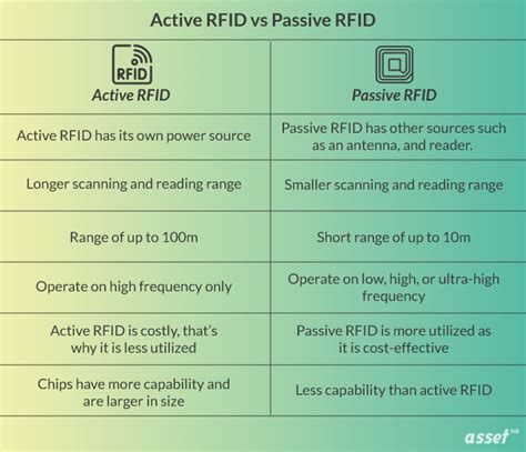
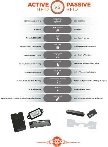
RFID reader is used to activate passive tag with RF energy and to extract information from the tag. For this function, the reader includes RF transmission, receiving and data decoding sections. In addition, the reader includes a serial communication (RS-232) capa-bility to communicate with the host computer. Depend-Passive. In a passive RFID system, the tags do not use a battery; instead, they receive their energy to run from the reader. The reader emits an energy field of a few feet, providing the energy for any tag in the vicinity.Passive RFID tags utilize an induced antenna coil voltage for operation. This induced AC voltage is rectified to provide a voltage source for the device. As the DC voltage reaches a certain level, the device starts operating.RFID Block Schematic: A simplified block schematic of an RFID tag (also called transponder) is shown in the diagram below. Various components of the tag are as shown. Normally, the antenna is external to the tag chip, and large in size.
Passive RFID tags derive all of their operating power from the energy of the RF field as absorbed by their antennae. This field is generated by another antenna connected to the RFID reader. Simple physics shows that field power decreases in proportion to the distance located from the (reader) antenna.
Passive RFID tags harness energy from an RFID reader’s emitted Radio-frequency (RF) signal. When the reader sends a signal, it creates an electromagnetic field that energizes the tag. The tag captures this energy and powers its internal chip, enabling it to transmit data back to the reader.
Four passive RFID tags based on low frequency are designed and implemented. The tags can be read by any RFID reader that operates on the low frequency range 125–134 kHz.Real and imaginary components of the impedance of the UHF RFID antennas depended on their design, coating composition and conditions of paper calendering. Passive UHF RFID tags were. When looking into implementing a passive RFID tag system into your business, one of the most important diagrams to have is the passive RFID tag schematic diagram. This diagram will show you the components that make up an RFID tag and how they work together.Passive RFID systems are composed of three components – an interrogator (reader), a passive tag, and a host computer. The tag is composed of an antenna coil and a silicon chip that includes basic modulation circuitry and non-volatile memory.
RFID reader is used to activate passive tag with RF energy and to extract information from the tag. For this function, the reader includes RF transmission, receiving and data decoding sections. In addition, the reader includes a serial communication (RS-232) capa-bility to communicate with the host computer. Depend-Passive. In a passive RFID system, the tags do not use a battery; instead, they receive their energy to run from the reader. The reader emits an energy field of a few feet, providing the energy for any tag in the vicinity.Passive RFID tags utilize an induced antenna coil voltage for operation. This induced AC voltage is rectified to provide a voltage source for the device. As the DC voltage reaches a certain level, the device starts operating.RFID Block Schematic: A simplified block schematic of an RFID tag (also called transponder) is shown in the diagram below. Various components of the tag are as shown. Normally, the antenna is external to the tag chip, and large in size.
Passive RFID tags derive all of their operating power from the energy of the RF field as absorbed by their antennae. This field is generated by another antenna connected to the RFID reader. Simple physics shows that field power decreases in proportion to the distance located from the (reader) antenna.Passive RFID tags harness energy from an RFID reader’s emitted Radio-frequency (RF) signal. When the reader sends a signal, it creates an electromagnetic field that energizes the tag. The tag captures this energy and powers its internal chip, enabling it to transmit data back to the reader.Four passive RFID tags based on low frequency are designed and implemented. The tags can be read by any RFID reader that operates on the low frequency range 125–134 kHz.

smallest passive rfid tag
rfid tags passive vs active

rfid passive tag cost
range of passive rfid tags
passive rfid tags for sale

Galaxy Nexus NFC antenna is on the battery. For some reason Samsung puts the NFC antenna in the battery of many phones. Because of that the extended battery can support NFC by just .
schematic of passive rfid tag|passive rfid tag price